
Scan tool Parameter Interpretation and Use
It is virtually impossible to successfully "improve" a turbo Buick beyond factory spec and hope to keep it together without a scan tool. Further, it will be impossible to tune it when using a modern, programmable chip. In fact, if one has an original, completely stock car, one will be ahead of the game if one has a scan tool given the age of the cars and the number of things that can go wrong.
One needs at a minimum, a scan tool, a means of measuring fuel pressure both at idle, and at wide open throttle, and an accurate means of reading boost....not the led's on the factory display (note that the digital dashed cars don't even have this). Against, I stress the word minimum.
The simplest scan tools connect to the ALDL port under the dash and monitor the data passing into and out of the ECM. The ECM controls virtually every aspect of the engine management system. Connection thru the ALDL port provides one frame of information every 1.4 seconds. On a very quick car, this is not very frequent, but there have been cars in the Nines using nothing more, but, this may not be adequate for the average guy that is lacking experience. Some tools, like the ScanMaster, are normally permanently mounted and are used all the time as a monitor.
The most comprehensive scan tools connect to the factory engineering connector on the bottom of the ECM which is normally covered by the ECM case. These units report data at a sample rate greater than 20 times per second as well as supplying many parameters that cannot be accessed thru the ALDL port. They provide data logging so that runs may be recorded on a laptop and replayed at a later time for tuning adjustments, and/or troubleshooting of problems. This is invaluable when it comes to performing an in depth analysis of the situation as well as making it easy for others to look at the data along with yourself.
PowerLogger is the latest such and its output may be directed to a ScanMaster to increase its data rate to five times per second as well as adding additional data that can be displayed on the ScanMaster. A laptop may be connected to it and several minutes of data may be recorded as well as providing a real time connection to many additional parameters not normally seen.
To my knowledge, the ScanMaster is the only scan tool specifically designed for the turbo Buick that is intended for full time use. Normally, it is permanently connected to the wiring going to the ECM although it may also be connected through the ALDL port if one wanted a mobile version. Again, I consider it absolutely essential if one wants to avoid disaster as much as is possible..which is never 100%, in any case. I do not like the free stuff like Winaldl. One has too much money tied up to trust it to something half-assed.
Below is the table of parameters available thru the ScanMaster which can be viewed....one at a time....on its display. This table is straight out of thee ScanMaster instruction booklet. These parameters are what can be expected from an intercooled car.
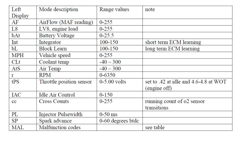
Before I address the above parameters, let me state that some of the parameters (primarily L8, Int, and BL) are specific to mass air set ups that are closed loop, and may be used for some other purpose by the programmer on those cars that are running open loop or speed density chips in the factory ECM.
Our cars originally came with Mass Air Flow sensors in the intake tract. This sensor measures the amount of air flow passing thru it and feeds that information to the ECM which uses it to determine a basis for fueling. The unit of measurement is grams per second which reflects mass. From the factory, the MAP sensor does nothing to affect fueling by the ECM. It only drives the digital boost gauge unless it is used in conjunction with an alky injection system by an aftermarket chip..
In recent years, some programmers such as Eric Marshall , Bob Bailey, and Steve Yaklin have devised means to eliminate the mass air sensor through the use of the speed density system when it is desired to do so. Speed density systems don't measure air flow per se. Instead, they use manifold air pressure and rpm to compute load and thereby fueling. In this case, the MAP sensor becomes an integral and necessary part of the fuel control system and need something like PowerLogger to feed the data into the ECM.
There are pros and cons to both systems, and there are plenty of articles available on the Net regarding such if one is interested in a more in depth understanding. For our cars, those in emission inspection states will probably do better with mass air set ups as the speed density chips concentrate more on all out performance and are not so concerned with passing an emissions check. I am currently running TurboTweak speed density chips in both my cars and like them, but, I have no emissions concerns at the moment.
Closed loop set ups use the feedback from the factory O2 sensor to adjust the base fueling programmed into the chip to maintain a stochiometric air fuel ratio at all times other than wide open throttle.
Open loop systems do not use feedback from the O2 to adjust fueling at part throttle, and, can be programmable so that the user determines fueling at all points of the operation.
Some chips may use a combination of open loop and closed loop operation such as an open loop at idle for smoother idle, and then closed loop off idle for better gas mileage, etc.
Some chips may also use input from a wideband O2 sensor to control fueling at wide open throttle, cruise, etc. in a closed loop mode.
It is important to read the instructions that come with the particular chip and understand what it is capable of if one wants to get the maximum benefit from the chip. If there is something that is not clear, don't be afraid to ask for clarification, or more information.
After writing the below, I found that Eric had written similar aimed at the PowerLogger. You might want to read his write up because he does not waste as many words as I do.
Enough digression, let's get back to the ScanMaster parameters shown in the table above.
The first thing I noted when I looked at them is that there is no mention on the table taken from the ScanMaster instructions of the default screen that is shown when the engine is started. This happens to be one of the most useful displays in day to day driving.
O2 voltage and Timing Retard
When the unit powers up, it displays the oxygen sensor voltage in millivolts on the left side of the display. The O.E.M. oxygen sensor is a narrow band unit that is only accurate at the stochiometric ratio for gasoline which represents an A/F of 14.7 to 1. On our cars, this is represented by an O2 reading of 441 mv as displayed on scan tools like ScanMaster, or PowerLogger. Voltage displayed less than this number are said to be Lean and voltages greater, are said to be Rich. But, there is a big catch here. Leaner or Richer refers to the stochiometric ratio which is 14.7-1. 14.7-1 is considered to be the most efficient burn of the air/fuel mixture when the fuel is gasoline. This has nothing to do with what ratio produces the most power. That ratio is a variable which depends upon the engine combination, amount of boost, timing, car weight, ambient conditions, etc. If your scan tool says rich or lean, it means in comparison to the ideal for best idle or cruise. It is not referring to wide open throttle operation.
As stated above, the factory oxygen sensor is only accurate at one point. Look at the NB O2 graph under Basics to see this visually. Other than in the crudest sense, the voltage display is basically meaningless when it comes to predicting A/F. However, we have been using it for years with the concept that the lowest voltage, that we can run without incurring detonation, is a target voltage.
My experience, with my particular cars/combinations, is that at wide open throttle, this is often around 780 mv when running on straight gasoline and somewhat lower...around 740-760 mv when spraying alky. These are wide open throttle numbers at speed in third gear. Now, go look at the factory O2 graph again and understand the futility of guessing a true A/F. Those who have installed wideband O2s that do provide an accurate A/F know how futile this actually is. Given that the output of the factory O2 is affected by heat and pressure, it is easy to see that 800 mv at part throttle may be several air fuel ratios different than 800 mv at wide open throttle.
At idle, with a closed loop chip, the 02s bounce around between 000 and 800 mv. With an open loop chip, they will be fairly stable around 770-800 mv.
In essence, then, at wide open throttle, we tend to run as lean as we can without incurring detonation as evidenced by timing retard and that is our target number for the moment.
Remember that use of Leaded Race Gas will drastically shorten the life of an O2 sensor and will affect the readings, sometimes after only a few runs. Some believe the Denso sensor will resist degradation longer than the factory AC. The Bosch wideband sensors don't like lead either and a short life can be expected when using leaded race gas. Be sure to read the Cross Counts paragraph further on.
Now, on the initial default, screen, there is a second parameter displayed when applicable. This is Timing Retard. Timing retard is shown on the right hand side of the display when the ECM "hears" detonation via the detonation sensor on the back of the engine by the coil mounting bracket. In my experience, when one actually hears detonation with his ears, damage has already been done, and the only real question is "How much Damage?". Before we hear it, the ECM has sensed it thru the detonation sensor input and has started reducing the amount of timing specified by the chip for wide open throttle operation. The number displayed is in degrees so that if one sees 3.8 on the ScanMaster display on the right side of the display, then one knows that 3.8 degs of timing is being pulled in response to what the ECM perceives as detonation. If the next frame of data that hits the ScanMaster now shows 7.3, then we know that the perceived detonation is increasing and the ECM has pulled even more timing trying to prevent damage. In all likelihood, the number will continue to increase if the detonation is real until one of two things happens. One, you lift off the gas, or, two, something breaks in the engine.
Now, everyone wants to know how much timing retard is safe. The correct answer is NONE. In the real world, two degrees of timing retard at 15 psi of boost will probably do very little damage whereas two degrees of timing retard, if allowed to continue, may pop a head gasket at 30 psi of boost. Two degrees of timing retard on a 300 hp car is not nearly as dangerous as two degrees on a 600 hp car. It is not the timing retard that causes the damage. It is the detonation that causes the timing retard that does the job.
In my opinion, the timing retard display on the ScanMaster is one of the most important functions as it is always there to be watched and is far more reliable than the light up, or audible, knock alarms. The money saved with this feature alone will be returned the first time you save yourself from a blown head gasket, broken crank, or rod thru the side of the engine. One never knows when an injector may not spray right, cause a lean condition, and cause a major problem if one is unable to watch this parameter.
Myself, I run an audible alarm in conjunction so I make sure something gets my attention and I get my foot out of it until I know what is happening. These knock alarms run off the raw data input and the warnings may not always be accurate, but, I know if I have not been getting and alarm, and then I suddenly do.....something has changed and it is time to find out what is going on.
AF = Mass Air Sensor Flow (MAF)
As stated at the beginning of this section, our cars come from the factory with a mass air form of fuel injection control which uses a flow meter, that we refer to as a mass air sensor, to measure the mass of the air flowing into the engine. Note that it measures mass and not volume. Hot air is less dense than cold air and thereby has less air molecules in a given volume than does the cold. Given that it is the number of air molecules in the cylinder that must be matched with fuel, it is important to know the mass.
The original factory mass air sensor is/was capable of measuring mass air flow from 3 to 150 grams per second. This is displayed on the scan tool over a range of some 3 to 255. 255 is numerical limit of the 8 bit processor in the ECM. The later LT-1/LS-1 mafs that can be used with Bob Bailey's Translator system can potentially flow a higher mass of air than the original units if the engine can use it.
This parameter is a big help in troubleshooting. One of the first suspects when the car is not idling/running correctly is often the MAF. This is particularly true if the original style MAF is being used. To verify operation, turn the key on, but do not start the engine. The AF on the scan tool will normally read 3. Then, start the engine. With a normal idle speed, it will normally read 4-6, and, may read 7 if the programmed idle is around 800/850 rpm as the faster idle will require more air thru the sensor. If the MAF is reading in this range, one can be pretty sure that it is not the problem that is causing the car to not run properly...particularly at idle.
Now, the MAF can also lose calibration at higher mass flows. As stated prior, 255 is the maximum number that can be displayed. Cars running boosts close to 15 psi or so may report less than 255..say 245, or thereabouts. As the boost gets closer to ~17 psi, the car will normally begin to max the reading out and one would expect to see 255, or very close. Design of the intake tract, engine size/combination, etc. will affect the actual number.
If one has been seeing 255 and then it starts reading 235, one may start having problems as one transitions to wide open throttle as the ECM believes the car is consuming less air and therefore provides less fuel.
If one has a logging scan tool such as PowerLogger, then the graph of the MAF output should be smooth with no spikes, or, sudden dips on a wide open throttle run.
The later style MAF/Translator systems are generally far more robust and don't cause many problems as long as the wiring is solid on the install.
L8 = LV8 (Load Variable 8 bit)
LV8 does not represent the output from a single sensor, but, rather is a computed number by the ECM which is used to represent engine load to supplement fueling as required. I "think" that the primary input is from the mass air number and rpm. I further "think" that the number calculated represents the mass of air pumped into an individual cylinder at any point of time. On speed density systems, the MAP sensor would be used to provide cylinder pressure as an indication of how much air the engine is consuming instead of the MAF which is not present.
As this number is not driven by an individual sensor, it is not one of the things we commonly pay attention to per se. It is of more use to the chip programmer who uses it to determine when, and how much, supplemental fueling is provided to obtain a satisfactory A/F ratio during acceleration. Load is an important factor in determining how much fuel an engine needs at a given time. An engine that is being revved in Park to 4000 rpm will need far less fuel than one being revved to 4000 rpm in Drive at wide open throttle. LV8 then is a major factor in deciding just how much is enough.
If one looks at some of the tuner software for EFI hardware, then one knows that fueling is a three dimensional process with an axis for fuel, rpm, and load. That is why a good programmer, or a good tuner is so important.
Fueling for 2000 rpm cruise is minimal as compared to fueling for 2000 rpm at wide open throttle. Obviously, in our cars, the amount of additional air being pumped due to the turbo is one of the variables that affect the amount required.
A Power Enrichment (PE) flag is shown on some scan tools and signifies when the chip is commanding additional fuel as the LV8 has surpassed a specified level.
bAT = Battery (actually the voltage seen at the ECM)
The voltage seen on the scan tool is the resultant of an analog to digital conversion by the ECM. It may be a couple of tenths less than the voltage measured with a meter at the back of the alternator due to resistance in the circuitry caused by bad connections, bad grounds, wire resistance, etc. Common problems are found in the ignition switch connectors and/or the fuse box (check the ecm-ign fuse in particular) where corrosion may form in the fuse holder. Of course one must have a good ground on the alternator (powder coated pieces may not transfer electrical current worth a darn) and good connections under the hood.
I like to see 13.5 volts, or higher, on the display at wide open throttle. If it drops below 13.0 then it is time to figure out why. As stated above, it may be a circuitry problem, or it may signal a failing alternator. Either way, it is telling us that the voltage being fed to the coil module is lower than optimum, and, we may end up with a weaker ignition spark than we would like to have if we are making a lot of power and need a good spark to fire the mixture in the cylinder.
If it is down in the 12 volt range, or less, than it would seem the alternator is not charging and we are on our way to a dead battery. That is definitely the time to find out why instead of on the side of the road at an inopportune time.
Int = Integrator (short term fueling adjustment)
Integrator (and the following section on BLMs) are both used by the ECM to control fueling such that the resultant A/F as close to the stochiometric ratio as possible in an attempt to minimize emissions and maximize fuel mileage as mentioned in the first section with regard to the O2 sensor. Note that we are discussing mass air systems as speed density does not use Integrators and BLMs.
For a comprehensive understanding of the process, go here and read Dave Huinker's (TurboDave) write up on GNTTYPE.
The ECM provides a fueling curve to the injectors based upon a programmed curve. The O2 sensor then reads the exhaust gas in order to determine how close to stochiometric the burn has been. Based upon the O2 sensor's output, the Integrator then continuously trims the programmed curve to move it closer to the ideal ratio. According to Dave's write up, this can be up to 20 times per second.
In a perfect world, the Integrator would read 128 at all times. The world is seldom perfect as conditions are continually changing. If the Integrator reads more than 128, then we know the ECM is adding additional fuel to richen the mixture to 14.7 A/F. If the number is less, then we know the ECM is removing fuel to lean the mixture down to the desired 14.7.
Generally, we tend to pay more attention to the BLMs than the Integrators as it is the end result and more indicative of the "correctness" of the overall fuel curve.
bL = BLMs (Block Learn Mode)
Again I strongly suggest you go here and read Dave's write up. It is not overly technical and is quite comprehensive. Again, these comments are for mass air set ups.
The Block Learn Mode serves to provide pre-programmed primary fueling up to the MAF maximum of 255. It consists of a 4x4 matrix (16 cells) that has MAF ranges on one side and RPM ranges across the top so that each cell in the matrix correlates to a given MAF range and a given RPM band. Fueling is dependent upon where in the matrix the car is operating.
Now this fueling is trimmed by the Integrators as derived from O2 sensor input as stated in the prior section. The BLM fueling is updated a couple of times per second so it is a longer term adjustment than that coming from the Integrators. The BLM fueling also has a limited capability to learn from the tweaks imposed and to update the fueling program over time to achieve the desired stochiometric ratio.
Again, if the fueling is spot on, then we will see 128 in all cells of the matrix. If we see the numbers closer to 150, then we know we have a problem and we should start looking for a problem due to a perceived leanness which is causing the ECM to add more fuel than would be expected. Problems could be in a number of places such as vacuum leaks, header leaks, a bad MAF, and so on.
If the number is closer to 100, then we know the system is running excessively rich and the ECM is reducing fuel trying to correct the problem, and once again, we know we have a potential problem that needs to be rectified and we look for problems that could make the car excessively rich.
Typically, if the numbers in the cells are 128 +/- 10, we consider this to be acceptable, and not necessarily indicative of a problem as it is well within the correction range of the ECM.
It should be stated again that there are 16 cells and that the number displayed on a scan tool such as the ScanMaster is only one cell that represents the current MAF vs RPM range.
MPH = Miles per Hour
This is the output from the VSS (vehicle speed sensor) mounted on the back of the speedometer. This may be used by the chip programmer to control converter lock up, or other functions. If it is, then it should read correctly. In the past when some used a 5/8's reducer in the speedometer cable in order to use the kilometer per hour markings on the speedometer as miles per hour, this could screw up such functions. Obviously, it should output the correct miles per hour and agree with the actual speedometer. If there is a problem, check with your chip programmer to see if it matters.
CLt = Coolant Temperature
This is the coolant temperature fed to the ECM by the ECM coolant temperature sensor mounted on the front end of the intake manifold on the drivers side. This is the sensor with two wires. The ECM varies fueling dependent upon coolant temp and it is very important that it reads correctly. If the sensor is bad and the ECM sees something like -40 degs, or similar, then the ECM will pour the fuel to the engine as it normally would in extremely cold weather and the result will be an extremely rich A/F, bad gas mileage, a poorly performing engine, and potentially, damage to the cylinders caused by the oil being washed off by all the gas.
AtS = Air Temperature Sensor
This is the intake air temperature sensor that the factory mounted between the air filter and the MAF. In the factory chips, it only affected fueling at very low temperatures. Some modern chips, particularly those made for Speed Density systems, may use it for fueling adjustments over the entire band so it should work correctly and provide the proper air temps to which it is exposed. Again, read the instructions that come with your chip and mount the sensor in the location specified if so indicated.
r = RPM
The RPM indicated on the scan tool will be accurate as compared to the rpm that is shown on the LED tach display if it still works.
tPS = Throttle Position Sensor
The TPS sensor tells the ECM where the butterfly in the throttle body is (how much it is open). The factory specs show a range of 0.35v-0.45v for the idle window and I have not seen a spec for wide open throttle, but, the stock chip code shows a voltage to turn off the AC compressor of 4.0v so that suggests that it should be greater than that. Programmable aftermarket chips will specify settings for both idle and wide open throttle in order for programming to work correctly and one should read the instructions that come with the chips and set the values according to the wishes of the programmer. Otherwise, there is not any real magic involved in setting the tps with regard to "magic numbers" passed down thru folk lore. See the Basics section for details on how to set tps voltages and note the relationship with the IAC settings.
On the scan tool, the TPS parameter should consistently show the same settings for both idle and wide open throttle with no floating, or changing of the values when the TPS is working correctly. Note that the values may be two tenths higher when the engine is running as opposed to the numbers seen with the engine off. This is normal. Do not set the idle value so that it goes out of range when the engine is running.
Further, when the key is on, engine off, the values should increment smoothly with no jumps, hops, or skips, as one slowly depresses the accelerator pedal to the mat. The TPS is essentially a variable resistor so no coils should be shorted out internally for proper operation.
IAC = Idle Air Control
At idle, the butterfly in the throttle body is essentially closed. The majority of the air used by the engine comes through the Idle Air Passage and is controlled by the Idle Air Control Solenoid. Look here for pictures of the components.
As the name suggests, the IAC is only meaningful at idle, on a fully warmed up engine with the AC off. If one has a problem and the readings of this parameter are in the range of 10-40 on the scan tool, then it is not the problem. Again note that it only affects idle quality. Some find that a steadier idle will be achieved with settings between 10-20. The lower the number, the less the IAC affects the idle control.
To determine if the IAC is functioning, one can observe the numbers when the engine is started. They should be higher than the warm engine setting and should drop as the engine is coming up to operating temperature. They should also increase when the car is put into gear from Park as the IAC solenoid increases its pulse count to provide more air in response to the increased load on the engine. The numbers when driving are meaningless as the engine is now getting its air through the butterfly opening.
Go here for instructions on setting the IAC counts and again note that this setting is interrelated with the TPS adjustment. Don't let adjustment to this parameter throw the TPS voltage outside the required window or the engine will not idle correctly.
Remember that idle speed is set by the ECM. The adjustment screw on the throttle body is for adjusting IAC's and not idle speed!
cc = Cross Counts
Cross Counts are the number of times that the factory O2 sensor has crossed from lean to rich across the stochiometric point (0.441v) during the sample rate of the scan tool. The more active the sensor is, the better job the ECM will do in keeping the A/F at the desired stochiometric ratio for idle and part throttle driving. At wide open throttle, it is not used. Many scan tools may show this number as a cumulative addition so that the first frame may be 10 and the second may be 30 which means the second frame was actually 20. When the total reaches 255, it resets to zero and starts over.
Given that a tool like the ScanMaster samples at approximately 1.4 second intervals and more sophisticated tools like PowerLogger may provide 20+ fps, one must take this into consideration when looking at the results.
Something like 10-40 cross counts per 1.5 seconds is probably normal. An O2 sensor that is sluggish and consistently is on the low end (count-wise) should be replaced. O2 sensors are cheap and it does not cost much to replace one periodically anyway. If you don't, gas mileage and drivability will soon go down hill.
As stated prior, leaded racing fuel will often drastically shorten the life of the O2 sensor. Symptoms are reduced output, sluggish cross counts, and/or a check engine light. Many believe the Denso sensors resist degradation much longer than do the factory AC sensors. When leaded gas has been used, even the Densos will show a sluggish cross count, but, will sometimes clean back up with use. Watch the counts, if they don't recover to a normal level, put another one in if you want optimum mileage and part throttle performance.
If you have a chip that provides an Open Loop idle, it will probably show zero cross counts at idle and this is normal. Check the cross counts at cruise. Also, do not expect cross counts at wide open throttle.
PL = Injector Pulse Width
(Not displayed on all chips)
This shows the pulse width fed to the injectors by the ECM. This number is in milliseconds and will be somewhere around 1.6-2.1 ms depending upon the injectors used when observing idle. The larger the injector, the shorter the time it will be help open at idle to obtain the correct amount of fuel. This parameter probably has little relevance to engine operation at most times.
SP = Spark Advance (Timing being commanded by the ECM)
(Not displayed on all chips)
This parameter shows the total timing being applied by the ECM for any part of operation. It will be high during cruise, and will drop down to the wide open throttle level under that condition. It can be used to compare the timing applied to what was programmed into the chip in case there is a doubt.
MAL = Malfunction Codes
Normally, this will be 0. If a trouble code has been set, then it will appear here. A 13, for instance would indicate that a trouble code 13 (Oxygen Sensor) has been set, and it is time to start troubleshooting. This is generally accompanied by a check engine light. Go here for troubleshooting procedures for each code that may be set. This is much easier than fiddling with a paperclip and counting blinks of the check engine light.
If I recall correctly, this shows up as NAL on my two ScanMasters.
---